The Basic Principles Of Wedge Barriers

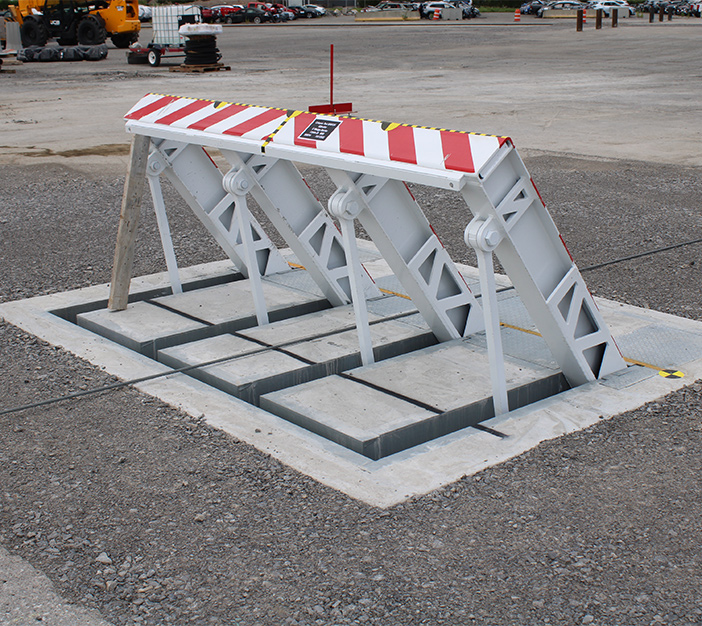
14 and the surface area 12 to which the obstacle 10 is protected may be made from concrete - Wedge Barriers. 2, the barrier 10 is placed to or includes an anchor or subframe (e. g., support 30 revealed in FIG. 2 )safeguarded underneath the surface area 12. For example, the bather 10 may be bolted to the support or protected to the anchor by various other mechanical fasteners. In the illustrated personification, the obstacle 10 consists of a wedge plate 16, which consists of a section that is significantly parallel with the surface 12 when the barrier 10 remains in the retracted setting. In various other words, lorries or individuals may overlook the barrier 10 when the obstacle 10 is in the pulled back setting and experience minor altitude about the surface area 12 while on the obstacle 10. As discussed carefully listed below, when the barrier 10 is in the released placement, the wedge plate 16 is held and supported in an increased placement by a lifting device of the obstacle 10. In addition, the elements 18 might be bolted or otherwise mechanically combined to one another. In this manner, repair work or replacement of one or even more components 18 might be simplified and structured. That is, repair service or substitute of single parts
18 may be done extra rapidly, conveniently, and price effectively. FIG. In certain personifications, the anchor 30 may be a steel framework including plates, beams(e. g., I-beams ), and/or other structures that are safeguarded within the structure 14, which may be concrete. At the surface 12, a top side 28 of the support 30 may go to least partly revealed
, thus making it possible for the attachment of the obstacle 10 to the support 30. g., threaded openings)in one or more beam of lights or plates of the support 30 might be exposed to the surface 12. In this manner, bolts 32 or various other mechanical fasteners may be made use of to secure the barrier 10 to the support 30. As the barrier 10 is installed to the surface area 12 of the structure 14, collection of particles and various other product below the obstacle might be lowered, and components of the bather 10 might not be revealed to listed below quality atmospheres. As indicated by reference numeral 52, the lifting system 50 includes components got rid of underneath the wedge plate 16. As an example, the components 52 underneath the wedge plate 16 might include an electromechanical actuator, a camera, one or more webcam surface areas, and so forth. In addition, the lifting device 50 includes a spring setting up 54
The springtime rod 58 is paired to a cam(e. g., webcam 80 displayed in FIG. 4) of the lifting device 50. The springs 60 disposed regarding the springtime pole 58 are kept in compression by springtime supports 62, consisting of a taken care of spring click here for more support 64. That is, the set springtime support 64 is dealt with family member to the structure 14 and the remainder of the bather 10.
Things about Wedge Barriers
g., spring support 65 )might be repaired to completion about his of the springtime rod 58 to make it possible for compression of the springs 60. As the springtimes 60 are compressed in between the springtime supports 62, the springtime setting up 54 generates a pressure acting upon the webcam paired to the spring pole 58 in an instructions 66. The continuing to be force applied to
the cam camera deploy release wedge plate 16 may might provided supplied an electromechanical actuator 84 or other various other. The spring assembly 54 and the actuator 84(e. g., electromechanical actuator)may run with each other to convert the cam and lift the wedge plate 16.
As stated above, the springtime setting up 54 applies a continuous pressure on the webcam, while the electromechanical actuator may be regulated to apply a variable pressure on the cam, therefore enabling the training and reducing( i. e., deploying and pulling back )of the wedge plate 16. In certain personifications, the consistent pressure used by the spring setting up 54 might be adjustable. g., electromechanical actuator) is disabled. As will be appreciated, the spring assembly 54 might be covered and safeguarded from particles or other elements by a cover plate(e. g., cover plate 68 received FIG. 4) that may be substantially flush with the elevated surface area 38 of the foundation 14. As discussed over, in the released position, the wedge plate 16 offers to obstruct gain access to or travel beyond the obstacle 10. The barrier 10(e. g., the wedge plate 16 )might block pedestrians or lorries from accessing a building or pathway. As reviewed above, the barrier 10 is connected to the support 30 protected within the foundation 14,
front braces 71. Because of this, the linkage assemblies 72 might pivot and turn to make it possible for the collapse and expansion of the linkage settings up 72 throughout retraction and release of the bather 10. The affiliation assemblies 72 reason activity of the wedge plate 16 to be restricted. If a vehicle is taking a trip towards the deployed wedge plate 16(e. For example, in one condition, the safety and security legs 86 might be extended duringmaintenance of the barrier 10. When the security legs 86 are released, the safety legs 86 sustain the weight of the wedge plate 16 versus the surface 12. As an outcome, the training device 50 may be shut down, serviced, removed, changed, and so forth. FIG. 5 is partial perspective view of an embodiment of the surface-mounted wedge-style barrier 10, highlighting the webcam 80 and the camera surfaces 82 of the training device 50. Particularly, two camera surfaces 82, which are referred to as reduced webcam surfaces 83, are positioned listed below the webcam 80. The lower webcam surface areas 83 might be repaired to the surface area 12 (e. For instance, the reduced cam surface areas 83 and the placing plate 85 might create a single piece that is protected to the support 30 by bolts or other mechanical fasteners. Furthermore, two camera surfaces 82, which are referred to as upper camera surface areas 87, are placed above the webcam 80 and coupled to (e. In various other embodiments, stepping in layers or plates might be placed between the surface area 12 and the reduced camera surface areas 83 and/or the wedge plate 16 and the upper camera surfaces 87 As pointed out over, the cam
80 equates along the camera surface areas 82 when the wedge plate 16 is raised from the pulled back position to the released setting. In addition, as pointed out over, the springtime assembly 54 (see FIG. 3 )may provide a force acting upon the camera 80 in the direction 102 through spring pole 58, which may decrease the pressure the electromechanical actuator 84 is needed to apply to the web cam 80 in order to activate and lift the wedge plate 16. 1 )to the released position(see FIG. 4). As shown, the camera 80 consists of track wheels 104(e. g., rollers), which get in touch with and equate along the cam surfaces 82 during procedure.